 It is difficult to verbally convey exactly what happens when an eyelet or grommet is set, so provided below is a step-by-step graphical representation of the process.
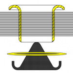
The drawing to the right illustrates the relative positions of the components in the setting process; the gray rectangle representing the material into which the eyelet is being set, the yellow disc being the washer (if used), and the black, irregular shape being the setting tool. The top setting tool has been omitted from these drawings for the sake of simplicity.
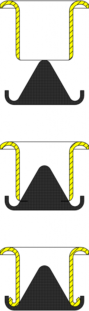 The first diagram to the left illustrates the cross-section of an eyelet descending onto a coiling tool. For the sake of simplicity, we have excluded the material and washer from these three diagrams.
Note that setting tools employ a top set and a bottom set. Usually, the coil is formed by the bottom set, though there are circumstances where the coil is formed by the top set.
In the second diagram, the eyelet hole is just starting to make contact with the setting tool. This is the point at which the coiling process is just about to begin.
In the third, we see how the configuration of the setting tool has caused the very end of the eyelet to turn up and inside out, creating the coil which is, in effect, another flange on the other side of the material, gripping either the other side of the material or a washer, if present.