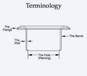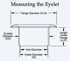
When a customer is speaking with a Stimpson customer service representative, it is helpful for both to be using the same terminology to avoid confusion. The diagram to the right illustrates the most important parts of every grommet and eyelet.
The flange is normally the most visible part of the eyelet or grommet because, when the part is set in the material, it is usually outward-facing.
The barrel is simply the tubular portion of the part that passes through the material. The barrel wall’s thickness is equal to the thickness of the metal used to produce the part.
The hole is where the setting tool turns the barrel inside-out to create the coil, securing the part in its application. The setting process is described in more detail later in this document.
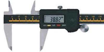
 When choosing a part, it is important to know which are the dimensions relevant to your application. The dimensions most pertinent to our customers are shown in the diagram to the left. Eyelet and grommet dimensions are generally measured in thousandths of inches (3 decimal places). Therefore, it is advisable to use precise measurement tools to determine Stimpson part dimensions. We recommend a caliper for all dimensions except I.D. and hole size, which should be measured using pin gauges.
Outside Diameter (O.D.) – We can start determining the barrel O.D. an application requires by first measuring the hole in the material into which the part is being inserted. The O.D. will need to be at least slightly smaller than the material’s hole so it will fit inside.
Inside Diameter (I.D.) – Some customers need to pass a rope or cord through the eyelet, in which case the I.D. is relevant. Most of our blueprints don’t directly specify an I.D., but it can be easily calculated by multiplying the metal thickness (i.e. wall thickness) by two, and subtracting that number from the O.D. It’s important to note that, due to how eyelets and grommets are produced, the hole diameter (aka “hole size”) is usually slightly narrower than the I.D. Once set, the hole becomes the outer rim of the coil, rendering its original size irrelevant.
Length Under Flange (L.U.F.) – As one might imagine, the distance between the bottom edge of the flange and the bottom hole of the eyelet must be long enough to pass through the material into which it will be set. However, since the bottom of the barrel will eventually be curling outward and up to secure the part in place, the L.U.F. will need to be roughly 1/16 of an inch longer than the thickness of the material into which the part will be set. This will accommodate the length lost to the formation of the coil during setting.
Flange Diameter (FLG) – The diameter of the flange is normally more of an aesthetic consideration than the other dimensions because the flange is usually the most visible portion of the part in the finished product. It is, however, also a practical consideration in cases where the part will be set in a flexible material. In these cases, it is advisable to choose a flange diameter that is large enough to prevent the part from slipping through the material.

